
The grounding resistance tester adopts the advanced medium and large scale integrated circuit, and uses DC/AC conversion technology to combine the measurement methods of three and four knobs into a new type of grounding resistance meter. The working principle is that the DC/AC converter inside the machine changes the DC into the low frequency constant current of THE AC, through the auxiliary grounding pole C and the measured object E constitute a loop, the measured object produces AC voltage drop, through the auxiliary grounding pole P into the AC amplifier amplification, and then through the detection into the meter head display. With the help of the rate switch, three different limits can be obtained: 0 ~ 2 ω, 0 ~ 20 ω, and 0 ~ 200 ω.
Grounding resistance tester is a major breakthrough of traditional grounding resistance measurement technology, widely used in electric power, telecommunications, meteorology, oil field, construction and industrial electrical equipment grounding resistance measurement. In the measurement of the grounding system with a loop, there is no need to disconnect the grounding lead line, no need for auxiliary electrode, easy to use. It can measure the grounding fault which cannot be measured by the traditional method, and can be applied to the occasion which cannot be measured by the traditional method, because the measurement is the combined value of the grounding body resistance and the grounding lead resistance.
Measuring steps of grounding resistance tester:
1) insert the two grounding probes into the ground 20m and 40m away from the grounding body along the radiation direction of the grounding body, and the insertion depth is 400mm.
2) Put the tester flat near the grounding body, and wire connection.
3) After placing the measuring instrument horizontally, check whether the pointer of the galvanometer points to the center line. Otherwise, adjust the "zero regulator" to make the pointer of the grounding resistance tester point to the center line.
4) The "multiplier scale" (or coarse adjustment knob) at the maximum multiple, and slowly turn the generator handle (pointer began to offset), while rotating the "measuring scale plate" (or fine adjustment knob) so that the galvanometer pointer to the center line.
5) When the pointer of the galvanometer is close to balance (the pointer is close to the center line), shake the handle to make the speed reach above 120r/min, and adjust the "measuring dial" to make the pointer point to the center line.
6) If the reading of the "measuring scale plate" is too small (less than 1), it is not easy to read accurately, indicating that the multiplier scale multiple is too large. At this time, the "multiplier scale" should be placed at a smaller multiple, readjust the "measuring dial" so that the pointer points to the center line and an accurate reading is read.
7) Calculate the measurement result, that is, R = "multiplier scale" reading x "measurement dial" reading.
Precautions for measurement:
(1) During measurement, the grounding device line should be disconnected from the protected equipment to ensure accurate measurement.
(2) If there is a metal pipe or cable connected with the measured grounding pole near the detection needle, the potential of the whole measurement area will have a certain equalization effect, affecting the measurement results. In this case, the distance between the current detection pin C and the metal pipe or cable should be greater than 100m, and the distance between the potential detection pin P 'and the metal pipe or cable should be greater than 50m. If the metal pipe or cable is not connected to the ground loop, the distance can be reduced by 1/2 to 2/3.
(3) When the sensitivity of the galvanometer is too high, the potential detection needle P 'can be inserted into the soil shallower; When the sensitivity of the galvanometer is insufficient, the soil between the potential probe needle P 'and the current probe needle C' can be moistened with water.
(4) when the distance between the grounding pole E and the current detection needle C 'is greater than 20m, the position of the potential detection needle P' can be inserted in the straight line between E 'and C', at this time the measurement error of the grounding resistance tester can be excluded; If the distance between the ground pole E 'and the current detection pin C' is less than 20m, insert the potential detection pin P 'between the straight line of E' and C '.
Electricity meter in the factory, maintenance, the need to carry out performance test, so the need to use the electricity meter field calibrator, the equipment in the process of use, often encounter a variety of failures, this article will give you a simple introduction to the electricity meter field calibrator common faults how to deal with.
1. During parameter measurement, the displayed value differs greatly from the actual value, so check whether the access voltage and current range are consistent with the actual value.
2, when measuring parameters, the display reading is not stable, should check the voltage input, in the absence of voltage input when measuring the current display reading will be unstable. In the case of voltage input, an unstable reading is load instability.
3. In the calibration process, if the error is very large, there may be the following reasons
4, wiring error, phase voltage and phase current are not corresponding, or phase power is negative.
5, when the photoelectric sampler missampling (that is, more or less samples), need to readjust the photoelectric sampler position or sensitivity.
6, the current input mode is not set correctly or three-phase three wire, three-phase four wire is not correct.
7, resulting in small end face dirty sampling current clamp current transformer core.
8. The iron core end face of the clamp type current transformer is not completely closed.
Ammeter constant input is incorrect.
10. Calibrate the variable ratio input error of the metering device.
11, the load of the field changes too much, or strong electromagnetic interference.
12, the low frequency output signal output and the low frequency constant of the standard electricity meter can be verified by the photoelectric pulse signal input on the calibration panel and the Pinend and GND terminals of the high and low frequency signal output. The error value read by the calibration method from the calibrator is equal to the absolute value of the actual error value of the calibrator, but the sign is opposite.
Power workers in the work, often need to use dc high voltage generator to boost the high voltage power equipment, the equipment is used very frequently, if you do not understand the function of each module on the panel, it is difficult to use the equipment well, this article will give you a brief introduction
How to interpret the functions of dc high voltage generator panel.
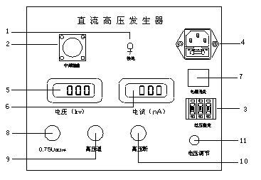
1. Ground terminal of control box: the ground terminal of control box and ground terminal of double pressure tube and sampling ground terminal are connected to the ground network after one point grounding.
2. Medium frequency and measurement cable quick access socket: mainly used for connection between chassis and voltage doubling part. When connecting, just press down the cable, turn the plug clockwise, and turn the cable plug counterclockwise when disconnecting the cable.
3, overvoltage setting switch: mainly used to set the overvoltage protection value. Dip switch display unit is kilovolt, set value is 1.1 times of the test voltage.
4. Power input socket: connect the randomly configured power cable to the power input socket. (AC 220 V +10%, socket has its own safety tube.)
5, digital display voltmeter: timely digital display of DC high voltage output voltage.
6, digital display ammeter: can digital display dc high voltage output current.
7, power switch: if the press before, turn on the power, red light. And vice versa.
8. Yellow light button: this function is designed for quick measurement of zinc oxide arrester 0.75 UDC1mA. Green light is effective. When the yellow button is pressed, the yellow light is on, and the output high voltage drops to the original 0.75%, keeping the state. Press the red button, the traffic light goes out, the high voltage is cut off, exit 0.75 times.
9, green button: this is the high pressure open button, high pressure indicator light. When the red light is on, press the green button, the green light is on and the red light is off, which means that the high voltage circuit is on and the voltage can be increased. This button is available only when the voltage regulator returns to zero. If the green button is pressed, the green indicator light is still on, but when the button is released, the green indicator light is off, indicating that the protection circuit in the machine is working.
10. Red light button: if the red light is on, it means the power is on and the high voltage is off. Press the red button when the green light is on. The green light changes to red and red, and the high-voltage circuit is cut.
11, voltage regulator potentiometer: potentiometer is a kind of multi-turn potentiometer. Rotate clockwise to lift and vice versa. The potentiometer has the function of controlling electronic zero position protection, which must be restored to zero before boosting the voltage.
Power workers use DC high voltage generator, it is necessary to make clear the function and principle of each block on the panel of DC high voltage generator in advance, so that when using, in order to know, easy to grasp.
Power transformer, generator, transformer, lightning arrester and so on high voltage electrical test equipment in the process of use for a long time, the need for insulation resistance testing on a regular basis, so you need to use insulation resistance tester, the equipment before use, need to do some preparation work and the basic operation of the insulation resistance tester test? This article will give you a brief introduction.
1. Before the test, the power supply and all external wires of the test equipment should be removed to make the test short circuit and discharge to the ground for 1 minute. If the capacitance is large, it should discharge for at least 2 minutes to avoid electric shock and affect the measurement results.
2. Clean the surface dirt of the tested object with a clean soft cloth. If necessary, clean the housing surface with gasoline to eliminate surface leakage current and affect test results.
3. The high voltage test strip is inserted into the line terminal of the red line (3), the green connector insertion end (2) and the plug end connected to the other end of the probe or fixture under the high voltage conductor device are tested. Subwire (green) of the test line to (2) GUARD end (right hand side), the other end of the cable ring device under test to eliminate the effect of leakage current on the surface (see "Shielding end Use" for additional black subwire the test line is inserted into the ground terminal (ground)
4. Before the test, the power supply and all external wires of the test equipment should be removed to make the test short circuit and discharge to the ground for 1 minute. If the capacitance is large, it should discharge for at least 2 minutes to avoid electric shock and affect the measurement results.
5, clean the test object with a clean, clean soft cloth dirt on the surface. If necessary, clean the shell surface with gasoline to eliminate the surface leakage current and affect the test results.
6. The high voltage test strip is inserted into the red line (3) line terminal, and the green connector insertion end (2) GUARD end and the other end of the probe or fixture are connected to the plug end of the high voltage conductor equipment under test. Subwire of the test line (green) to the (2) GUARD end (right hand side), the other end on the hV cable ring device to be measured, to eliminate the effect of leakage current on the surface (see "Shielding end Use" for additional black subwire test wire is inserted into the ground terminal (ground).
Power workers in the work, often need to use insulation resistance tester, the device is also a very conventional high voltage power test equipment, power workers in the use of the equipment before the preparation work to do, so as to get twice the result with half the effort.
The company is committed to intelligent three-phase microcomputer relay protection tester r & D, production, sales of high-tech enterprises, the company has a solid technical force, in the product structure, software, hardware and electrical control and other core technology has accumulated a wealth of project experience, with novel design to please users. Your details are welcome.
Three-phase microcomputer relay protection tester operation method:
1. Install the built-in industrial computer and Windows operating system. Do not switch on and off the host power too frequently.
2. A USB port is installed on the installation panel or backplane. The USB device (such as a USB flash drive) can be hot-switched.
3. Install a dedicated self-recovery CF card to prevent operating system damage caused by illegal shutdown, deletion or correction of files on the hard disk and ICONS on the desktop. If you really need to store data in the machine, please save the data in drive D. When copying data using USB disk, please ensure that the USB disk is clean without virus, and please do not use the USB disk to install other software programs in the system.
4. When you connect an external keyboard or mouse, do not insert it incorrectly; otherwise, the Windows operating system may fail to start.
Now many industries are used to the gas recovery unit, which represented by SF6 gas recovery unit has always been a hot, users in the use of these gas recovery unit should know before the use of relevant considerations, such not only ensure the desired results, at the same time for itself is a kind of the equipment maintenance and maintenance, and please smart star said this today The topic.
One, before using SF6 gas recovery unit should make sure the correctness of the connection parts, and the sealing of the interface, only properly connected and enough seal can normal use of equipment, as well as in the process of using, vacuum pump is cannot be reversed, and should attach great importance to the oil level of components, specific SF6 gas recovery unit components have fixed to oil level O.
Two, in the use of SF6 gas recovery device to recover gas half an hour before the refrigeration system should be opened, and it should be noted that the refrigeration system just opened when there may be condensed water discharge, timely treatment of this problem. Otherwise, when the SF6 gas recovery device is used, the refrigeration system is turned on again. At this time, it is more troublesome to deal with the condensed water, so the refrigeration system should be turned on in advance.
3, when using SF6 gas recovery unit to pay attention to the change of molecular sieve, the description of equipment own use replacement cycle, such as using ten thousand hours after the replacement of molecular sieve, and is also must pay attention to the filter cartridge replacement, normally filter cartridge replacement cycle is five thousand hours for a replacement, and make specific change frequency reference With instructions, and the replacement of molecular sieve and filter element is the equipment specified model and brand. Just mentioned what time is the use of SF6 gas recovery unit should pay attention to the matters needing attention, and now a lot of type gas recovery unit, the function different, so should be read carefully before using such devices form a complete set of instructions and maintenance manuals, so as to ensure good results, and can achieve the service life of equipment.
Modern people can't live without electricity. Factories need electricity for production, homes need electricity, offices need electricity, entertainment needs electricity. The power system equipment is complicated, once the failure occurs, the fault situation is complex, troubleshooting is difficult, to people's production and life also bring great inconvenience.
1. Familiar with circuit principle and determine maintenance plan:
When the electrical system of the equipment fails, do not rush to remove it. First, understand the symptom, process, scope, and cause of the fault. Familiar with basic working principle of equipment and electrical system, analyze each specific circuit. Make clear the connection between all levels of the circuit and signal in the circuit of the ins and outs, combined with practical experience, after careful thinking, determine a scientific overhaul program.
In the debugging of the cable fault locator to find the cable fault point, it is necessary to fully communicate with the cable management technical personnel first, obtain relevant information effectively, and make maintenance plans. Firstly, the cable fault type is judged according to the measured insulation resistance, and then the test method is judged. Only in this way can we achieve "twice the result with half the effort", otherwise it is often "twice the effort with half the effort".
2. Pre-loss, post-circuit:
Power equipment is based on the principle of electrical machinery, especially the advanced equipment of mechanical and electrical integration, mechanical and electronic organic coordination in function, is two parts of a whole. Often mechanical components fail, affecting electrical systems, and many electrical components fail to function. Therefore, do not be confused by the surface phenomenon, the failure of the electrical system is not all the electrical itself, may be caused by the failure of mechanical parts. Therefore, before troubleshooting electrical components, it is often twice as effective to repair mechanical system failures.
3. Simple before complex:
The maintenance and repair of faults should adopt simple and feasible methods, followed by complex and accurate methods. During troubleshooting, you need to troubleshoot the intuitive, obvious, simple, and common faults first, and then troubleshoot the difficult and unhandled faults.
4. Repair common diseases first and attack incurable diseases later:
Power equipment is often prone to the same type of failure, is the "common failure". Because common failures are common and have accumulated a wealth of experience, they can be eliminated quickly. In this way, we can concentrate our energy and time to eliminate rare, difficult and odd difficult diseases, simplify steps, narrow the scope and improve the speed of maintenance.
5. External debugging before internal processing:
Exterior means the exterior of the various switches, buttons, sockets and indicators exposed to the exterior of the electrical equipment to complete the seal. The interior refers to the printed circuit boards, components, and various wiring within the housing or seal of electrical equipment. External debugging first, then internal processing, is in the case of electrical equipment without disassembly, the use of switches, travel buttons, buttons on the panel of electrical equipment debugging inspection, reduce the scope of failure. First eliminate the external components caused by the fault, and then repair the machine fault, as far as possible to avoid unnecessary disassembly.
6. First no power measurement, then power test:
First, in the absence of power supply to repair the power equipment: confirm that there is power, and then in the presence of power supply to repair and confirm the power equipment. For many faulty electrical equipment maintenance, can not be immediately energized, otherwise it will artificially expand the scope of failure, burn more components, resulting in undue loss. Therefore, before the faulty machine is powered on. Resistance measurement should be carried out first, and necessary measures should be taken before power maintenance.
7. Public circuit first, then special circuit:
If the common circuit of any electrical system fails, its energy and information cannot be transmitted and distributed to each particular particular circuit. The function of the particular circuit will be affected and its performance will not work. If the power supply of an electrical equipment fails, the whole system cannot run normally, and the energy and information transmitted to various special circuits cannot be realized. So follow the order of public circuit first, then special circuit, can quickly and accurately eliminate the fault of electrical equipment.
8. Sum up experience and improve efficiency
With the increasing demand of the current loop resistance tester market, in recent years, the manufacturers of this kind of equipment have developed rapidly, some customers have the actual demand to buy, but because of the lack of common sense in the professional field before, and then in many types of loop resistance tester do not know how to accurately buy, The following is to introduce the loop resistance tester when you need to investigate the purchase of matters.
First, specific types of products. Of choose and buy when the loop resistance tester, you must first understand their real demand of choose and buy, because of the different types of loop resistance tester, the use of the specific environment and the request is not the same, recommend the actual process of choose and buy, should be detailed inspection equipment of the engine power, communication, continuous working time, important technical parameters such as accuracy, Be sure to choose the right circuit resistance tester for you.
Second, the quality of products and services. Service quality is the choose and buy when the loop resistance tester need inspection items, loop resistance tester is a kind of relatively professional equipment, will inevitably be later in the process of using equipment failure problems, which requires equipment have more perfect after-sales service system, to avoid the late because of equipment failure problems and bring greater losses.
Third, product customer evaluation. Customer feedback is when the choose and buy should not be ignored, in general, the customer evaluation is generally good loop resistance tester, the quality of its use in the late relatively more worthy of the broad masses of customer trust, that we must attach great importance to, the actual when the choose and buy should be consulting products equipment, to ensure the quality of device type pass, service in place.
The above is about the purchase of loop resistance tester needs to consider the matters introduced, has been committed to the development of high-quality loop resistance tester, product types are diverse, the quality of service is in place, customer feedback is good, if you have the real demand for the purchase of loop resistance tester later.
In many operations will use the circuit resistance tester, and the current function of the resistance tester is also increasing with the increase of the model, but there are also a lot of people to buy the time to buy the functional equipment, so today please intelligent star about the basic function as a resistance tester should have what.
A, the loop resistance tester type many, now and at the time of purchase should pay attention to the basic function of the project, including testing loop in the circuit of L - and L - N and L - PE L circuit short circuit impedance short-circuit current and expected measured quadrupole method can be used, and pay attention to the two levels of large current measurement method is to 42. A, The level 4 test is 280A, which is a basic function.
Two, now the loop resistance tester not only more stable operation, and the test will be more stable, such as when testing the loop impedance to ensure the accuracy of the results and frequency is up to standard, and for the test results can be stored and transmitted to the computer through data lines, etc., In the current computer popularity today, this is the loop resistance tester should have the basic function.
Three, because the technology is mature so the current circuit resistance tester generally has the characteristics of a wide range of measurement, such as the current tester can be measured in 220V and 380V and 230V and 400V voltage environment, it can be said that the vast majority of the power grid environment can meet the measurement needs of the circuit resistance tester, It can also measure AC voltage and calculate expected circuit short circuit.
Four, if it is a little intelligent or a new type of circuit resistance tester can also directly calculate the expected short circuit and short circuit current can also distinguish phase current and line voltage, at the same time to complete the automatic adjustment range. Just mentioned is the current circuit resistance tester should have the function, in fact, just mentioned are more basic functions of the tester, so in the purchase of the time just mentioned belongs to the object to be investigated, and then according to the specific measurement needs to select specific functions.
Inverter is composed of main loop, power loop, IPM drive and protection loop, cooling fan and so on. Its structure is mostly unitary or modular form. Due to the incorrect use method or unreasonable setting environment, it is easy to cause the misoperation and failure of the frequency converter, or fail to meet the expected operation effect. It is important to analyze the cause of failure carefully in advance to prevent it from happening.
1. Analysis of common faults of the main loop
The main circuit is mainly composed of three-phase or single-phase rectifier bridge, smoothing capacitor, filter capacitor, IPM inverter bridge, current limiting resistor, contactor and other components. Many of these common faults are caused by electrolytic capacitors. The life of electrolytic capacitor is mainly determined by the DC voltage and internal temperature added at both ends. The type of capacitor has been selected in the circuit design, so the internal temperature plays a decisive role in the life of electrolytic capacitor. The electrolytic capacitor will directly affect the service life of the frequency converter. Generally, the service life will be halved every time the temperature rises by 10℃. Therefore, on the one hand, proper ambient temperature should be considered during installation, and on the other hand, measures can be taken to reduce pulsating current. Using ac or DC reactors with improved power factor can reduce the pulsating current and thus prolong the life of electrolytic capacitors.
During capacitor maintenance, the deterioration of the electrolytic capacitor is usually judged by the electrostatic capacity that is easy to measure. When the electrostatic capacity is less than 80% of the rated value and the insulation impedance is less than 5 M ω, the electrolytic capacitor should be replaced.
2. Typical fault analysis of main loop
Fault phenomenon: frequency converter in acceleration, deceleration or normal operation of overcurrent trip.
First of all, it should be distinguished whether it is caused by load or frequency converter. If it is the fault of the frequency converter, the current at the time of tripping can be queried through the historical record. It exceeds the rated current of the frequency converter or the set value of the electronic thermal relay, and the three-phase voltage and current are balanced. It should be considered whether there is overload or mutation, such as motor blocking. When the load inertia is large, the acceleration time can be appropriately extended, and this process does not damage the converter itself. If the tripping current is within the rated current of the frequency converter or within the setting range of the electronic thermal relay, it can be judged that the IPM module or related parts have failed. Firstly, the positive and negative resistors between the output terminals U, V and W of the main loop of the frequency converter and the P and N terminals of the DC side can be measured to determine whether the IPM module is damaged. If the module is not damaged, the drive circuit is faulty. If IPM module overcurrent or inverter short circuit trip to the ground when decelerating, it is generally the inverter's upper half bridge module or its drive circuit fault; When the IPM module overflows during acceleration, it is the module of the lower half bridge or part of its drive circuit failure. The reasons for these failures are mostly caused by the external dust entering the inverter or the humidity in the environment.
3. Control loop fault analysis
It is the power supply part of the control circuit that affects the life of the inverter, which is the buffer capacitor in the smooth capacitor and IPM circuit board. The principle is the same as the above, but the pulsating current passing through the capacitor here is a constant value that is basically not affected by the load of the main circuit, so its life is mainly determined by temperature and power time. Because the capacitors are welded on the circuit board, it is difficult to judge the deterioration situation by measuring the electrostatic capacity. Generally, according to the ambient temperature and service time of the capacitor, it is estimated whether it is close to its service life.
The power supply circuit board provides power to the control circuit, IPM drive circuit, surface operation display board and fan, etc. These power supplies are generally from the main circuit output DC voltage, through the switching power supply and then rectification respectively. Therefore, a short circuit of a power supply may affect other parts of the power supply in addition to the damage of the rectifier circuit. For example, due to misoperation, the control power supply is short-connected to the public ground, resulting in partial damage to the switching power supply on the power circuit board, and the short circuit of the fan power supply leads to other power supplies. Generally by observing the power circuit board is relatively easy to find.
The logic control circuit board is the core of the inverter, which integrates the CPU, MPU, RAM, EEPROM and other large-scale integrated circuits. It has high reliability, and the probability of failure is very small, but sometimes all the control terminals will be closed at the same time due to the startup, resulting in EEPROM failure of the inverter. This is done by simply resetting the EEPROM.
IPM circuit board contains drive and buffer circuit, as well as over voltage, lack of equal protection circuit. The PWM signal from the logic control board is input to the IPM module through optical coupling, so the optical coupling on the IPM module should be measured while the mode speed is detected.
4. Cooling system
The cooling system mainly includes heat sink and cooling fan. Among them, the cooling fan has a short life. When it is near the service life, the fan vibrates and stops after the noise increases. IPM overheating and tripping of the inverter occurs. The life of the cooling fan is trapped by the bearing, about 10000 ~ 35,000 h. When the frequency converter runs continuously, it is necessary to replace the fan or bearing every 2 to 3 years. To extend the life of fans, some products have fans that only run when the converter is running, not when the power is on.
5. External electromagnetic induction interference
If there are interference sources around the frequency converter, they will invade the internal of the frequency converter through radiation or power line, cause the control loop misaction, resulting in abnormal work or shutdown, and even damage the frequency converter in serious cases. Specific methods to reduce noise interference include: all relays and contactor control coils around the frequency converter should be equipped with absorption devices to prevent impulse voltage, such as RC surge absorber, whose wiring should not exceed 20 cm; Shorten the wiring distance of the control loop as far as possible, and separate it from the main loop; The distance between the wiring hinge of the inverter control loop should be above 15 mm, and the distance between it and the main loop should be above 10 cm; When the frequency converter is far away from the motor (more than 100 m), on the one hand, the cross sectional area of the wire can be increased to ensure that the line voltage drop is within 2%. At the same time, the output reactor of the frequency converter should be installed to compensate for the charging current of the distributed capacitance generated by the long distance wire. The grounding terminal of the frequency converter shall be grounded according to the provisions, and shall be reliably grounded at the special ground point. It cannot be used together with electric welding and power grounding. The frequency converter input is installed with a radio noise filter to reduce the input of high harmonics, so as to reduce the impact of noise from power line to electronic equipment; At the same time, a radio noise filter is installed at the output end of the converter to reduce the line noise at the output end.
6. Installation environment
Frequency converter belongs to electronic device, in its manual has detailed installation environment requirements. In special cases, if these requirements can not be met, the corresponding suppression measures should be adopted as far as possible: vibration is the main cause of mechanical damage to electronic devices, for the occasion of large vibration impact, rubber and other vibration avoidance measures should be used; Damp, corrosive gas and dust will cause corrosion of electronic devices, poor contact, insulation reduction and short circuit, as a preventive measure, should be anti-corrosion and dustproof treatment of the control board, and the use of closed structure; Temperature is an important factor affecting the service life and reliability of electronic devices, especially semiconductor devices. Air conditioners should be installed according to the environmental conditions required by the device or avoid direct sunlight.
In addition to the above points, it is also necessary to regularly check the air filter and cooling fan of the frequency converter. For special cold occasion, in order to prevent the microprocessor from working properly due to low temperature, necessary measures such as setting air heater should be taken.
7. The power supply is abnormal
Power supply anomalies can be divided into the following three kinds, namely, phase loss, low voltage, power failure, and sometimes their mixed forms. These anomalies are mostly caused by wind, snow and lightning strikes on transmission lines, and sometimes by ground and phase short circuits in the same power supply system. Lightning strikes vary greatly by region and season. In addition to voltage fluctuations, some power grids or self-generating units will also have frequency fluctuations, and these phenomena sometimes occur repeatedly in a short period of time. In order to ensure the normal operation of equipment, corresponding requirements are also put forward for the power supply of frequency converter.
If there are directly started motor and induction cooker equipment nearby, in order to prevent the voltage reduction caused by the input of these equipment, the power supply should be separated from the power supply of the frequency converter to reduce the mutual influence.
For the equipment that requires instantaneous power failure to continue to operate, in addition to the selection of a suitable price of frequency converter, the speed reduction ratio of the motor load should also be considered in advance. When the inverter and the external control loop adopt the instantaneous power outage compensation mode, after the loss of voltage recovery, the speed measuring motor is used to prevent the over-current in acceleration.
For equipment requiring continuous operation, the frequency converter should be equipped with an automatic switching power supply device. For example, the inverter with diode input and the use of single-phase control power supply, although in the state of phase loss, but also can continue to work, but the current of individual devices in the rectifier is too large, and the pulse current of the capacitor is too large, if the long-term operation will cause adverse effects on the life and reliability of the inverter, should be checked and treated as soon as possible.
8. Lightning strike, inductive lightning
The impulse voltage formed by lightning strike or induced lightning strike will sometimes cause the damage of the converter. In addition, when the primary side of the power supply system has a vacuum circuit breaker, the short circuit will produce a higher impulse voltage. In order to prevent overvoltage damage caused by impulse voltage, it is usually necessary to pressurize sensitive resistance and other absorption devices at the input end of the frequency converter. RC surge absorber shall be added to vacuum circuit breaker. If there is a vacuum circuit breaker at the primary side of the transformer, the inverter should be disconnected before the vacuum circuit breaker is operated in the control sequence.


 Home
Home Tel
Tel Product